Chapter 35 - Building Construction
Learning Objectives
At the completion of this chapter, students will be able to do the following:
1) List at least one common structural material used in residential construction.
2) Identify at least one type of roofing system.
35.1 Key Terms
Transcript
This chapter is designed to help students better understand the various components that make up residential buildings. When you are viewing a house (or residential building), it is important to have a good understanding of how the building is constructed.
As a future practicing real estate agent there are several benefits this chapter has to offer:
- First, you will gain a deeper insight into the construction and materials used in the buildings you sell or rent.
- Second, you will be able to better communicate and provide insight into the major building elements to your client.
- Finally, you will be able to better identify problems (or opportunities) with a building.
This chapter is broken down into several lessons. Each lesson addresses a building component or system.
Let’s start by going over several key terms that you will encounter throughout the chapter.
Beam - A horizontal structural element. Joists, trusses, and girders are examples of a beam.
Column - A vertical structural element.
Concrete Masonry Unit (CMU) - A block of hardened concrete, with or without hollow cores, designed to be laid in the same manner as a brick or stone. Concrete masonry units are commonly used in load bearing exterior walls.
Flashing - A thin, continuous sheet of metal, plastic, rubber, or waterproofing used to prevent the passage of water through a joint in a wall, roof, or chimney.
Footing - The widened part of a foundation that spreads a load from the building across a broader area of soil.
Foundation - The portion of a building that has the sole purpose of transmitting structural loads from the building into the earth.
Frost Line - Depth in the earth to which the soil can be expected to freeze during a severe winter. In New York State, the frost line ranges from 4’-0” - 5’-0” below the ground.
Joist - One of a parallel array of light, closely spaced beams used to support a floor deck or flat roof.
Lintel - A beam that carries the load of a wall across a window or door opening. Also referred to as a header.
Load Bearing Wall - Walls that support the floor or roof of a building. Load bearing walls are considered structural walls and help transfer the load of a building down to the foundation and footings.
Parapet - The portion of an exterior wall that projects above the level of the roof.
Partition - An interior non-load bearing wall. Partitions are typically comprised of wood or metal studs with gypsum board on either side.
Party Wall - A structural wall that is shared between two adjoining properties. Party walls are commonly built using concrete masonry units; however, many older buildings use brick.
Rafter - A framing member that runs up and down the slope of a steep roof.
Shingled Roofing - A type of roof covering that consists of individual overlapping elements. These elements typically consist of wood, slate, asphalt, metal, plastic, or composite material.
Sill - The strip of wood that lies immediately on top of a concrete or masonry foundation in wood frame construction. The sill also refers to the horizontal bottom portion of a window.
Single-ply Roofing - Roofing systems that are composed of insulation, a single-ply membrane, flashing and adhesive. The three most common types of single-ply membranes include TPO, EPDM, and PVD.
Stud - One of an array of small, closely spaced, parallel wall framing members. Studs are made of wood or metal.
Wythe - A vertical layer of masonry that is one masonry unit thick.
Key Terms
35.2 Structural Materials Used in Residential Construction
Transcript
Let’s begin by discussing several of the most common structural materials used in residential construction.
The first is dimensional lumber.
Dimensional lumber refers to wood members that are cut to a pre-defined size and used in framing wooden buildings. Wood members include wall studs, floor joists, roof rafters, and furring members.
Dimensional lumber used for structural elements is made of softwoods, as opposed to hardwoods which are used for veneers.
You may have heard of wood studs referred to as 2x4, or 2x8, or 2x10, etc..
These are nominal numbers that are referring to the width and depth dimensions (in inches) of the wood member. The length of the member is specified separately. So, a 2x4 can be 8’-0” (eight feet), 10’-0” (ten feet), 12’-0” (twelve feet) long, etc..
However, it is important to note that the nominal size is NOT the actual size of the member. The actual size is always less than the nominal.
For example, A 2x4 actually measures 1 ½” x 3 ½” (one and a half feet by three and a half inches), while a 2x10 actually measures 1 ½” x 9 ¼” (one and a half feet by nine and one quarter inches).
There are several pros and cons to dimensional lumber.
Wood frame construction offers several sustainable benefits. It is a renewable material that is energy efficient, as its heat loss is significantly less compared to steel or concrete.
Wood frame construction is also quicker (and many times cheaper) to build.
On the downside; however, wood frame construction is susceptible to mold and termites. It is not fire resistant, and it is not as strong, and durable compared to steel or concrete construction. Finally, since wood is a natural material, every wood member is not the same. Some wood members may have slight imperfections.
Next, let’s go over cold-formed metal framing, which has become increasingly popular as a structural material in recent years.
The alternative to wood members is cold-formed metal framing (also known as light gauge metal framing).
Cold-formed metal framing is made of galvanized sheet steel that is rolled or pressed into shapes that can be used for construction.
In North America, member types have been divided into five major categories, which include:
- S members, which are lipped channels, used for wall studs, floor joists, and ceiling or roof rafters. S members have punched openings at the center of the web to allow for electrical conduits and/or pipes to pass through walls and above ceilings.
The size of an S member is similar to that of a wood member. The typical depth ranges from 2 ½” - 14” (two and a half inches to fourteen inches), depending on the span of the floor or height of the wall. The difference is that metal framing uses exact dimensions, rather than nominal dimensions.
- T members, which are unlipped channels, are used for top and bottom tracks in walls. T members are also used at the heads and sills of windows.
- U members and unlipped channels that have a smaller depth than tracks, but are used to brace members, as well as for ceiling support systems.
- F members, also known as ‘furring’ or ‘hat’ channels, are typically used horizontally on walls or ceilings. It is common to see F members used to help finish the interior face of a masonry wall. The furring channels get fastened to the masonry wall and gypsum board is then screwed to the furring channels.
Furring channels are typically ⅞” or 1 ½” (seven eights inches or one and a half inches) deep.
- L members are angles, which in some cases can be used for headers across openings to distribute loads to the adjacent jamb studs.
Like dimensional lumber, there are several pros and cons to using cold-formed metal framing.
Cold-formed metal framing offers several advantages compared to wood framing, including durability, consistency, strength, and stability. Metal framing is also corrosion resistant, fire resistant, termite-proof, not susceptible to mold, and made with recycled materials. However, metal framing is more labor intensive due to the difficulty of fastening the steel connections.
The last structural material we’ll cover are concrete masonry units.
Concrete masonry units, also known as CMU or concrete blocks, are blocks of concrete that are made from cast concrete. CMU is produced with hollow centers to reduce weight, allow for vertical reinforcing, and improve insulation.
CMU is used to build walls (typically load bearing walls) and the individual blocks allow structures to be built in the traditional masonry style with layers (or courses) of staggered blocks.
CMU are bound using a cement based mortar, and in many cases, horizontal and vertical reinforcing are used. When reinforcing is used, the cores in the CMU are filled with grout. CMU walls can also be partially grouted (every other cell is filled with grout), or not use grout at all. It ultimately depends on the structural loads imposed on the CMU wall.
The most common CMU size is 16”x8”x8”, whose actual dimensions are 15 ⅝”x7 ⅝”x7 ⅝”. The actual dimensions of CMU are made ⅜” less than the nominal dimensions. However, the mortar joints are typically ⅜” thick.
CMU construction offers many advantages compared to other materials (especially wood frame construction) including:
- More durability.
- Fire, mold, and insect resistance.
- Acts as a good sound and thermal insulator, especially when the cells are grouted.
- It’s sustainable as it’s made of recycled materials.
- And, it typically allows for a speedy construction.
On the downside, CMU has several disadvantages, such as:
- It’s a labor intensive material; and,
- It requires more space since insulation must be provided on the surface of the CMU (as compared to metal or wood framing where the insulation can be provided between the studs).
Key Terms
PLEASE REVIEW THE DOCUMENT BELOW:

35.3 Structural Systems
Transcript
Now that we have reviewed the primary materials used in residential construction, we will next discuss the typical structural systems you will encounter in residential buildings. You will learn how the materials mentioned previously are used in the structure of a building.
The structure is the ‘bones’ of the building and must be built first. Once the structure is in place, and the building is enclosed, waterproofed, and insulated, the remainder of building essentially consists of finishes that satisfy the aesthetic desires of the owner.
The structural systems of a building are usually permanent, and therefore expensive to modify, while the finishes of a building are more easily modified, depending on the owner’s desires.
The structural systems are responsible for transferring the load of a building down to the earth.
Building loads consist of dead loads and live loads.
Dead loads, also referred to as a gravity load, is essentially the load of the building itself. It consists of the weight of the materials used to construct the building plus any permanent fixtures.
Live loads are temporary loads imposed by people, furniture, or the weather (such as loads imposed by wind or snow).
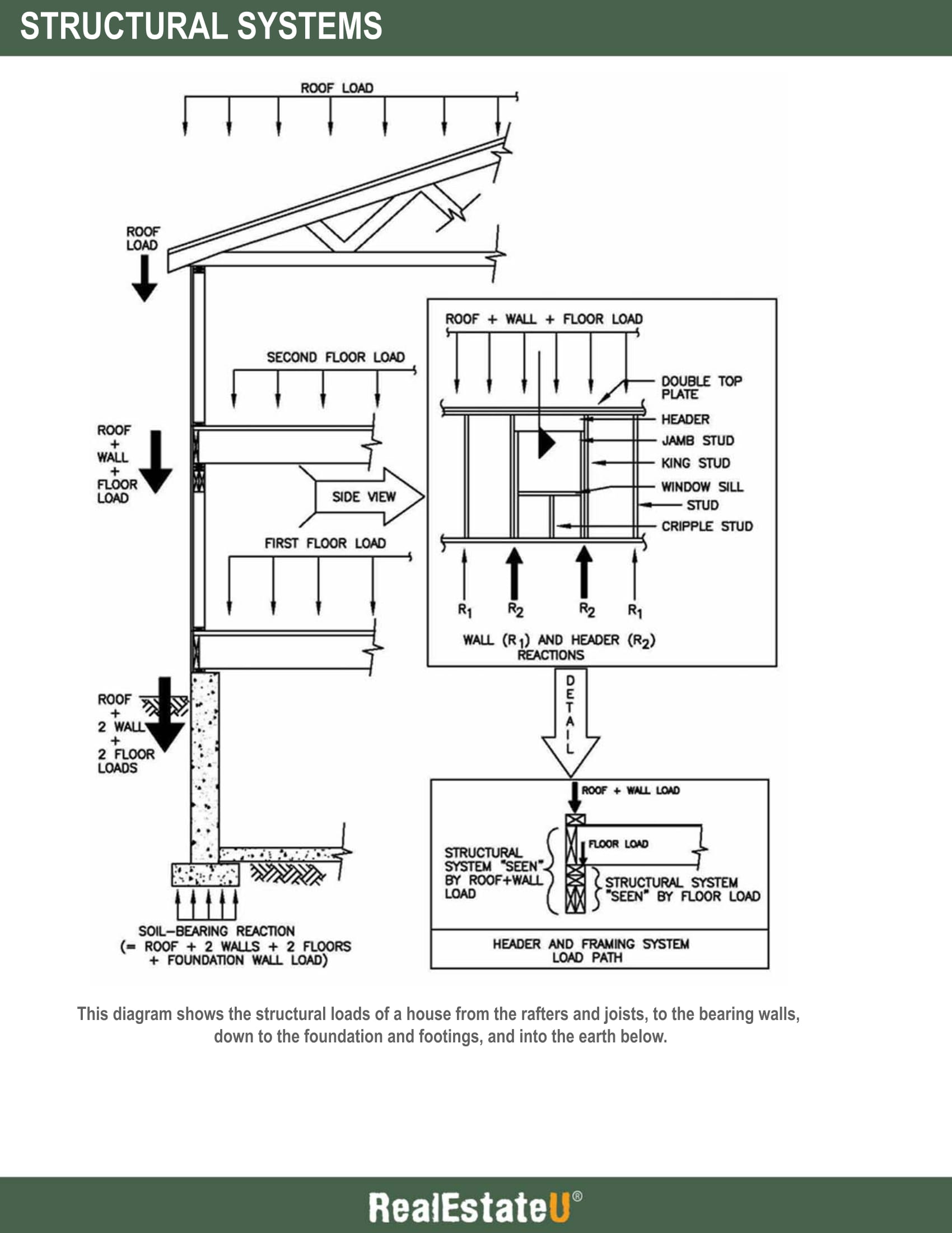
In any building, you can trace the distribution of structural loads from the rafters and joists, to the bearing walls, down to the foundation and footings, and into the earth below, where the load is counteracted by soil or bedrock.
The structural system consists of a variety of components. These include (starting from the top of the building down to the earth):
- Roof rafters
- Floor joists or beams
- Load bearing walls (both exterior and interior) or columns
- Foundation walls
- Footings
Before we discuss the various structural components of a building, let’s first learn about two fundamental components, namely, a beam and a column.
You may have heard the terms beam and column used in many different contexts; however, the concept of each is very simple.
A beam is a horizontal structural element, while a column is a vertical structural element.
A beam may include a joist, girder, steel beam, truss, etc..
A column may include a steel column, post, concrete column, etc..
We will now discuss each structural component in detail.
Let’s begin by going over roof rafters.
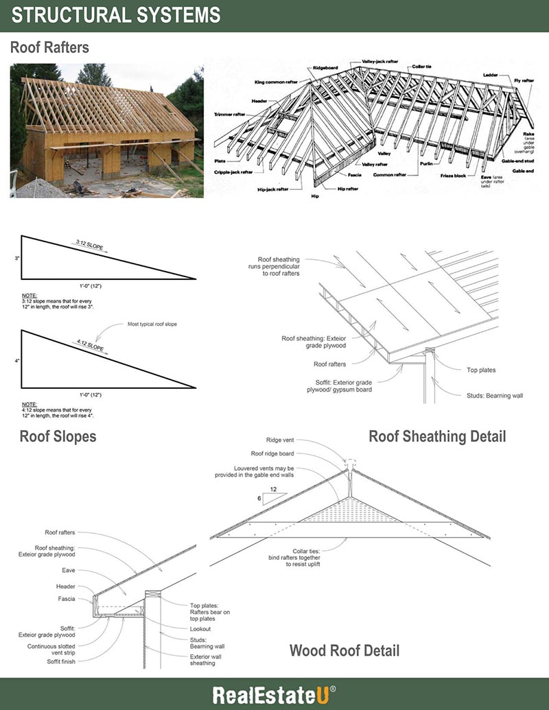
Roof rafters are the main structural support for a sloping roof. Rafters are made of dimensional lumber (wood) or cold-formed metal framing, and spaced 12”, 16”, or 24” on center.
The slope of a roof is referred to as its pitch. The pitch of a roof is expressed as a ratio of inches of rise per foot of run. For example, a pitch may be labeled 4:12 (or 4/12) or 6:12 (or 6/12), which are the most common roof pitches.
Sloping roofs are generally identified as a low slope roof and normal slope roof. Low slope roofs range from 3:12 to 4:12, while normal slope roofs are 4:12 and up.
Let’s go over the components of a sloped roof.
The rafters are fastened to a ridge beam (also referred to as a ridge board) at the top of the roof, forming the ridge of the roof.
Hip (or valley) rafters are used at the diagonal intersection of planes.
Jack rafters are common rafters cut off at varying lengths to meet a hip (or valley) rafter.
The entire rafter system is supported on top plates, which form the top of the bearing wall below. The roof rafters can also be supported by CMU walls.
The idea is that any dead load (the weight of the roof itself) and live load (weight of snow or moisture) is transferred by the rafters, down to the top plate, and into the bearing walls below.
The roof rafters are covered by what is called sheathing, or exterior grade plywood. The sheathing is fastened to the rafters and encloses the roof. It also enhances the stiffness of the rafter framing and provides a base for which various roofing materials can be applied.
Sheathing generally consists of ⅝” or ¾” thick exterior grade plywood. The sheathing boards should run perpendicular to the roof rafters.
Next, we’ll discuss the eave, soffit and fascia.
The overhanging (or cantilevered) lower edge of the roof rafters, over the exterior wall, forms what is known as an eave. The eave may extend beyond the exterior wall a few inches to a few feet. Eaves help keep rain water off the exterior walls and prevent the ingress of water at the junction where the roof meets the wall. Eaves can also contribute to a passive solar building design, as it helps prevent sunlight from hitting the exterior wall (or even windows).
The underside of the roof eave is known as the soffit. The soffit is typically enclosed using exterior grade plywood or gypsum board. The plywood or gypsum board is then finished using a variety of materials, including vinyl, wood, stucco, or metal. The soffit finish may reflect the material used on the exterior wall or roof. Many soffits include vents that provide the needed air flow for the roof and attic space.
The face of the eave is known as the fascia. The fascia is the broad, flat surface of the outer edge of a roof. The fascia is typically made of wood and nailed to a wooden header member. The fascia is then finished using a variety of materials, similar to those used for the soffit.
The next structural component we’ll discuss are floor joists.
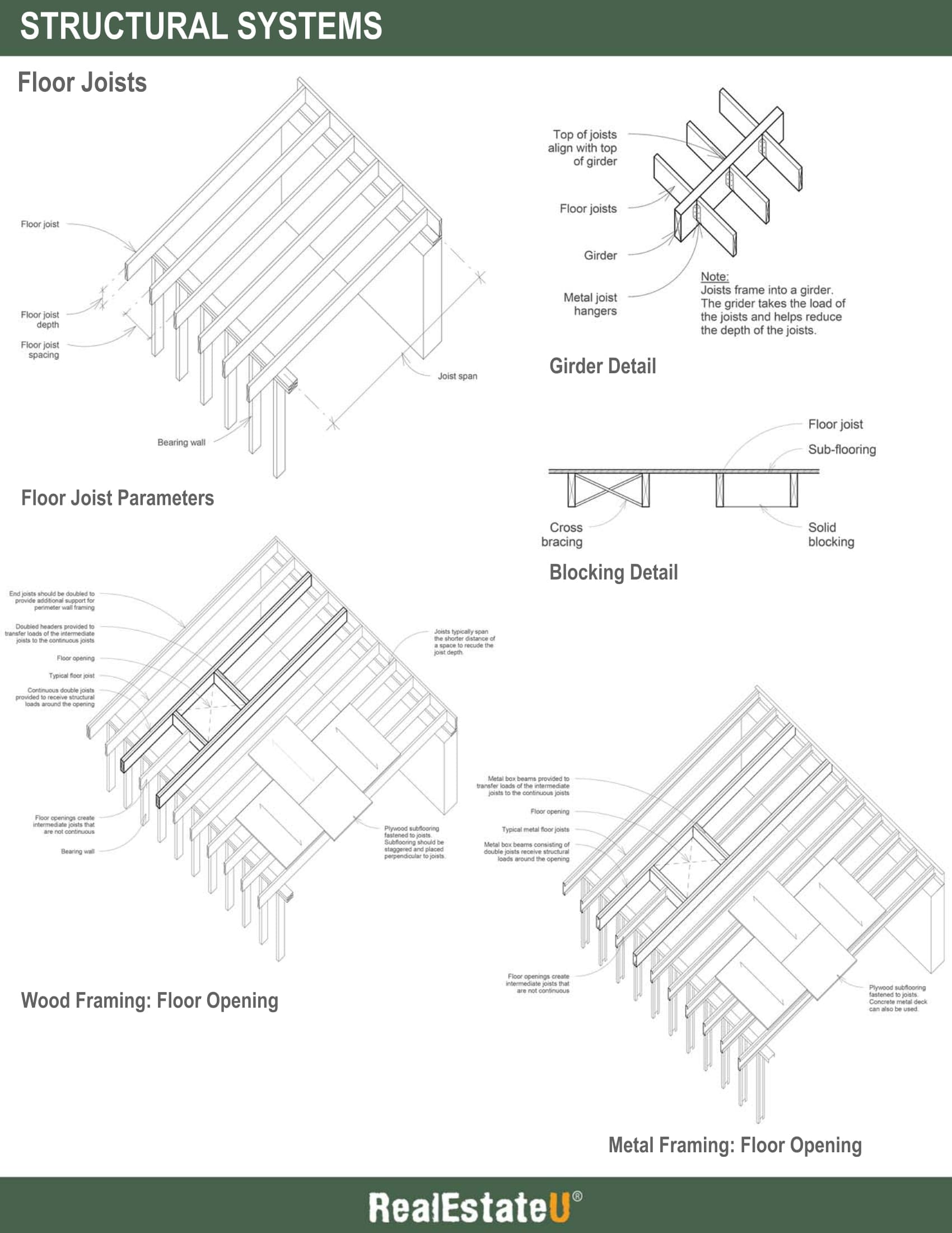
Floors in residential buildings are supported by floor joists. Floor joists are made of wood members or cold-formed metal members.
Joists span between bearing walls (or foundation walls). They are designed to transfer the dead and live loads of a floor to the bearing walls. The required depth of the joists varies, depending on the span. The longer the span, the deeper the joist.
Ultimately, the required depth should be calculated by a structural engineer; however, there is a rule of thumb that can be used. For wood joists, the depth of the joists is equal to half the span (in feet) plus 2 inches.
For example, the joist depth required for a 20 foot span is 12 inches (20/2 = 10 + 2 = 12).
Wood joists are typically 2” wide (1 ½” actual width). For example, wood joists can be 2x8, 2x10, 2x12, etc..
Metal joists are typically 1 3/4 ” or 3” wide, with depths similar to wood joists.
The spacing between joists varies depending on the span and load imposed on the floor, however, typical spacing includes 12”, 16”, or 24” on center. If smaller joists are used over a long span, a 12” spacing between joists may be needed. Ultimately, the floor loading, span, and spacing are used to determine the correct joist depth.
Joists typically want to span the shortest distance between bearing walls to avoid having deep members. When an Architect is in the process of designing a building, he or she will want to identify the location of bearing walls to allow joists to span the shortest distance of a space. If this can’t be accomplished in certain parts of the building, the Architect may decide to introduce a girder, or an additional interior bearing wall, rather than using deeper joist members.
In addition to joists, you should also be aware of another structural floor component known as a girder. Girders in residential construction are made of wood, metal, or steel. Girders are primary beams in which smaller beams (or joists) frame into.
The important point to note is that joists are framed into girders, or in other words, a girder transfers the load of a joist. For this reason, the depth of a girder is deeper than that of a joist.
They are typically supported by bearing walls or columns.
Girders are used for several reasons. First, the span of a space may be too long to make the use of joists feasible. The solution is to provide a single, deep girder that spans the entire space, and have the joists frame into the girder. This reduces the span of the joists.
Second, there may not be a bearing wall at one end of the joists. The solution is to span a girder between two columns (or bearing walls) and have the joists frame into the girder on one end.
It is sometimes necessary to install bracing or blocking between floor joists. Bracing will stiffen the floor system, prevent joists from twisting, and increase the overall stability in the floor system.
Bracing consists of wood or metal cross-bracing or full-depth blocking placed between the joists at 8’-0” intervals.
Once the joists are built, the subflooring must be built over the joists. Subflooring is the structural material that spans across the floor joists, serves as a working platform during construction, and provides a base for the finish floor.
Subflooring typically consists of sheets of ⅝” or ¾” plywood, depending on the spacing of the joists. The plywood is laid perpendicular to the floor joists. Blocking is sometimes added where two pieces of plywood subflooring meet.
When cold-formed metal joists are used, concrete metal deck may be used in place of plywood. Concrete metal deck is a composite flooring system that includes metal deck, topped with poured-in-place concrete. Metal decking is made of light gauge corrugated steel. Concrete metal deck typically includes a 1 ½” or 3” metal deck, topped with 3” of reinforced concrete. The corrugated metal deck must run perpendicular to the metal joists.
When openings are provided in floors (typically for stairs), additional framing or reinforcing is needed.
When wood joists are used, the two closest joists to the opening are doubled up to provide additional support. Intermediate beams (again, consisting of doubled up wood members) run perpendicular to the joists to form the opening. The idea behind the doubling up of joists/beams is that the opening prevents several joists from spanning between supports. The perpendicular beams are needed to transfer the load of the unsupported joists to the adjoining joists, which in turn, transfers the load to bearing walls.
The same applies to openings in metal joist floors. The joists around the opening are doubled up to create a box beam. The box beams transfer the loads of the unsupported joists to the adjacent joists.
The next structural component we’ll cover are bearing walls.
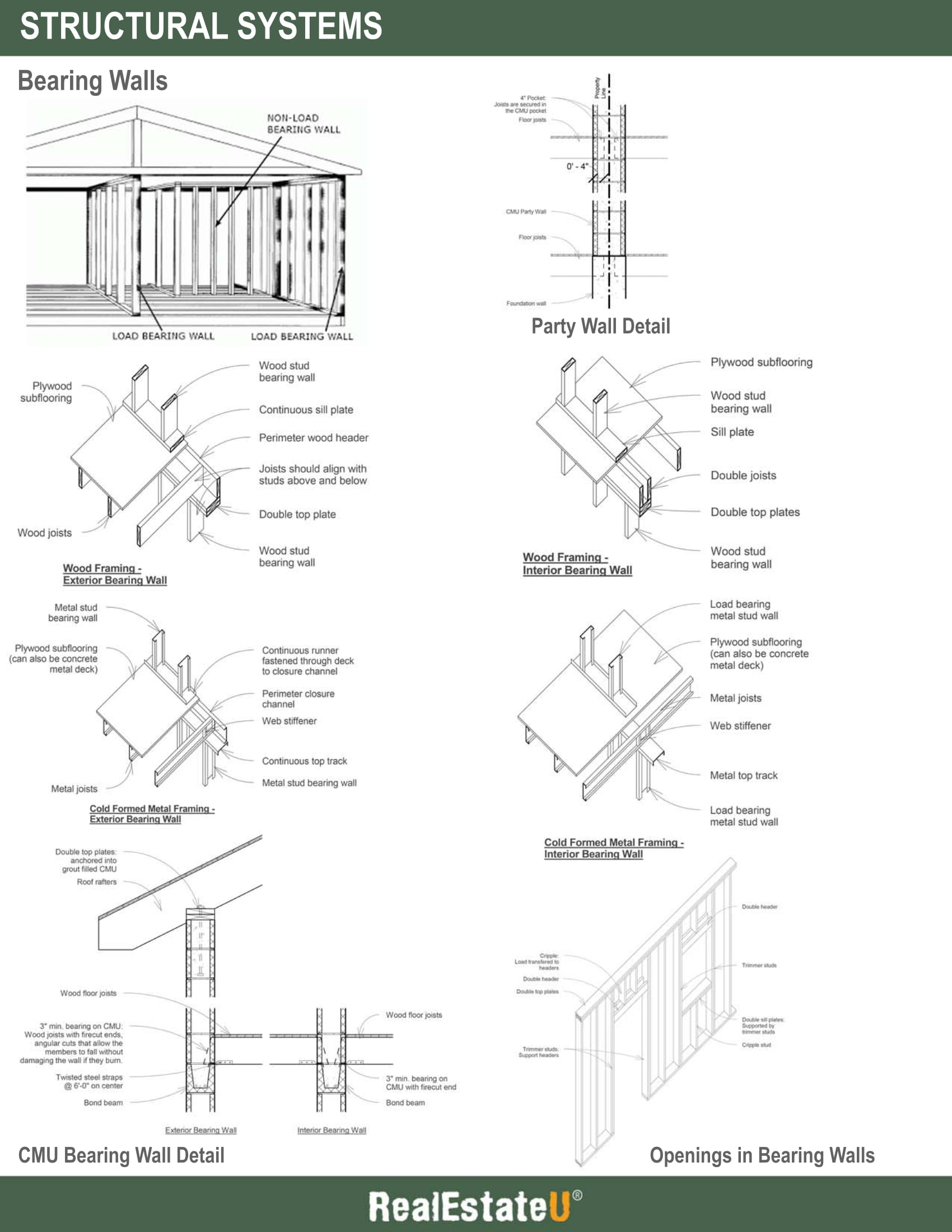
Bearing walls are one of the most important structural components in a house. Nearly all residential buildings use bearing walls as the primary vertical structural element.
Bearing walls are typically constructed of wood frame, cold-formed metal frame, or CMU. In older residential construction, it is common to see bearing walls built of solid brick construction, rather than CMU.
In most residential construction, the exterior walls of the building are load bearing walls.
The purpose of the load bearing walls are to transfer the loads of the roof rafters and floor joists down to the foundation walls.
A party wall is a structural wall that is shared between two adjoining properties. You commonly see party walls in townhouses.
Party walls are typically built of CMU since CMU walls not only allow joists to be framed from both sides, but also provide a fire barrier between the two buildings.
How can you identify a bearing wall?
Bearing walls are continuous, up and down the building. If you see the floor joists (or girders) framed into a wall (both exterior and/or interior), that wall is most likely load bearing. If you can’t see the joists, you can make an educated guess as to which way the joists are spanning. Joists typically span the shortest distance of a room or space, as discussed previously.
How are bearing walls constructed?
As mentioned above, bearing walls in residential construction are typically built using wood framing, metal framing, or CMU.
Wood framed bearing walls typically include 2x6, 2x8, or 2x10 studs, placed 16” or 24” on center. A sill plate is used at the bottom of the studs, while two top plates are fastened to the top of the studs. Both the sill and top plates will be the same size as the studs. The floor joists then sit on top of the top plates and should be aligned with the studs of the wall. The next level of the bearing wall is then built on top of the joists.
Cold-formed metal framing bearing walls typically use studs with 5 ½”, 6”, 8”, or 10” deep webs, with flange sizes ranging from 1 ⅜” - 2 ½”. Like wood framing, the studs are spaced 16” or 24” on center, and the joists should align with the studs. The metal studs are fastened to tracks at the top and bottom (U shaped members) with the joists sitting on top of the top track.
CMU bearing walls typically use 6”, 8”, or 12” (nominal dimensions) wide blocks. The CMU cells are commonly grouted, and both vertical and horizontal reinforcing may be added if the loads imposed on the CMU demand reinforcing. When floor joists or roof rafters bear on the CMU wall, a fully grouted and reinforced bond beam is used below.
Since bearing walls are responsible for transferring vertical loads, the number of openings in the wall for doors and windows are typically limited.
When an opening (door or window) is provided, a beam must be inserted to transfer the loads around the opening.
In wood frame or cold-formed metal framing, the beam above an opening is known as a header. In wood frame construction, the header consists of two members ranging from 2x4s to 2x12s.
In cold-formed metal framing, the header consists of two S members to form a box beam (discussed earlier).
A similar detail is used at the bottom of a window opening.
The studs at either side of an opening are doubled-up, to help carry the additional loads. This is the same concept used in floor openings, where the joists are doubled-up.
When an opening is made in a CMU wall, the beam used to span the opening is known as a lintel. Lintels are made of steel angles, whose size depends on the length of the span.
Next, let’s discuss foundation walls, another major structural component of any residential building.
Underneath all bearing walls (and columns) are foundation walls. The primary function of foundation walls is to transfer the loads of the bearing walls down to the footings. Foundation walls are mostly located below grade; however, it is common to see the top part of a foundation wall come a few feet above grade, especially when supporting wood construction.
It is important to slope the finish grade away from the foundation to help prevent any excess water (rain or melting snow) from draining into the foundation.
In addition to supporting the loads of the superstructure above, the walls must be able to withstand the horizontal loads imposed by soil (as well as water) around the foundation.
How are foundation walls constructed?
Foundation walls are almost always made of reinforced cast-in-place concrete. The concrete should be at least 8” thick, but most walls are 12” thick and reinforced both vertically and horizontally with steel rebar.
Taller foundation walls may be 18” or even 24” thick.
At the top of the foundation wall is a pressure treated wood sill plate, typically 2x6 or 2x8, which are secured using steel anchor bolts. The anchor bolts are cast into the foundation wall and then the sill plate is secured. The joists of the first floor and header (or rim joists) are then fastened to the sill plate. The sill plate essentially acts as a transition piece between the foundation and the superstructure.
When the superstructure is built of cold-formed metal framing, a steel clip angle is bolted to the foundation wall. The perimeter channel, joists, and web stiffeners are then fastened to the clip angle.
If you see any cracks in the foundation wall, it is most likely due to settlement issues. Cracks in a foundation wall can be a series issue as it is usually not easy to remedy the cause and prevent additional cracking.
Finally, let’s discuss footings.
Beneath every foundation wall are footings, which spread the load from the building across a broader area of soil. The primary function of a footing is to transfer the load of the building down into the earth.
Footing are always wider than the foundation walls. They are made of cast-in-place concrete and typically measure 12” deep by 24” wide and get keyed into the foundation wall. Footings in larger buildings may measure 24” deep and 36”-48” wide, since larger building loads need to be distributed.
The reason footings are wider than the foundation walls is because a larger surface area is needed to distribute loads into the earth below. Think of the concept of a nail. The point of the nail is extremely narrow and sharp. This way, when a hammer strikes the nail, the entire force is eventually transferred to the tip of the nail, which allows it to penetrate a wood surface.
If the foundation wall is not widened at the bottom, forming the footing, it will essentially act like a nail. The entire load of the building above will ultimately find its way to the bottom of the foundation wall, which has a relatively small surface area. The result will be an unstable foundation.
When discussing footings, it’s important to understand the frost line.
The bottom of every footing must be at, or below, the frost line. The frost line is the depth at which water in soil will freeze in the winter. Below the frost line, the temperature of the soil and water remains relatively stable throughout the year.
Water expands when frozen and contracts when unfrozen. If the footing is built above the frost line, it will be exposed to the expansion and contraction of soil water. This expansion and contraction will create movement beneath the footings, which leads to an unstable building foundation. The result can be cracks in the foundation wall and differential settlement.
Key Terms
PLEASE REVIEW THE DOCUMENTS BELOW:
35.4 Roofing Systems
Transcript
In this lesson, we’ll discuss roofing systems in residential buildings and their components.
Let’s start by going over the various roof finishes you may encounter in residential construction.
The most common sloped roof finish are shingles. Roof shingles are flat, rectangular shapes that are laid in courses from the bottom edge of the roof up, with each successive course overlapping the joints below.
Roof shingles consist of the following types:
- Asphalt shingles (the most common)
- Wood shingles
- Fiberglass shingles
- Wood shakes; and,
- Slate shingles
Asphalt shingles are the most widely used residential roofing material, primarily because they are inexpensive and easy to install. Asphalt shingles either have an organic felt base, or an inorganic fiberglass base.
Organic based shingles are saturated with asphalt to make it waterproof, then a top coating of adhesive asphalt is applied, and ceramic granules are then embedded. Organic shingles offer only moderate resistance to fire. Fiberglass based shingles consist of glass fiber reinforced mat that is coated with asphalt. Fiberglass shingles offer excellent fire resistance.
Most asphalt shingles have tabs with a self-sealing adhesive or locking tabs that make them wind-resistant.
Beneath the roof shingles is an asphalt-saturated felt underlayment that temporarily protects the roof sheathing during construction, and also offers additional protection from wind-driven rain. A single layer of underlayment is provided on normal slope roofs, while a double layer is provided on low slope roofs.
While shingled roofs are inexpensive, light-weight, and easy to install, they often face durability issues. Shingles may be susceptible to large degrees of expansion and contraction, leading to cracking. Shingle roofs typically required regular maintenance and repair. Finally, asphalt shingles are not environmentally friendly.
Next, there is tile roofing. Tile roofing consists of clay or concrete units that overlap or interlock to create a textural pattern.
The most popular tile roofs include Mission or Spanish tile, which are tapered, semi-cylindrical roofing tiles laid convex side up to overlap flanking, similar tiles laid concave side up.
A roofing felt underlayment is included beneath the tiles.
The minimum slope of a tile roof should be 4:12.
Tile roofing offers excellent fire resistance, are very durable, and require little maintenance.
However, tile roofing is very heavy, and requires additional rafter support.
Next, we have metal roofing. Metal roofing is characterized by sheets of metal, whose seams are interlocked to create a strong visual pattern. Metal roofs are made of a variety of materials, the two most common being copper and corrugated (or ribbed) panels.
Copper roofing offers a very compelling aesthetic, which through its natural weathering process, turns from a warm bronze tone to a green patina finish.
Copper is extremely durable and requires little maintenance. Once installed, copper will not require painting or finishing. On the downside, however, copper is very expensive, which leads to a high upfront cost.
There are a variety of seams used in copper roofs, including a standing seam and a lap seam.
Standing seams are made by folding up the adjoining edges against each other, then folding their upper portion over in the same direction.
Lock seams are made by folding up the adjoining edges against each other, folding them over, and flattening the interlock.
The seams are typically spaced 12” to 24” on center. The recommended minimum slope of a copper roof is 3:12. Anything less may require soldered seams (rather than folded seams).
Corrugated metal roofing consists of ribbed panels that span between roof rafters and fastened to the plywood sheathing or intermediate purlins. Metal panels typically consist of aluminum or galvanized steel.
The recommended minimum slope is 3:12.
Metal roofs are economical and easy to install; however, they are not as durable as copper roofs and often require more upkeep.
Next, we’ll discuss ventilation of a roof.
It is very important to provide roofing ventilation. Venting the roof and attic space accomplishes several things, depending on the season.
In the summer months, venting helps expel solar-heated air from the attic or roof, which reduces the cooling load for the building. Throughout the day, the building is constantly absorbing heat which combines with the heat generated within the building from people, appliances, lighting, etc.. The heat will ultimately rise to the top of the building where it needs to be expelled.
In the colder, winter months, venting helps prevent ice dams from forming on the roof by maintaining a cold roof temperature. The idea is that if the roof is not vented, warm air from the living spaces will make its way to the roof and melt the snow. The melted snow may then freeze during the night. In a vented roof, cold air is continuously moving beneath the roof, preventing the roof from heating up.
Roof and attic ventilation is accomplished passively by using continuous vents at the soffit and ridge of the roof. An air space is provided from the soffit vent to the ridge vent. The air space must be at least 1”, but a 2” air space is often recommended. Sheathing and insulation should be used to make the space below the vented roof air tight. This ensures that hot air does not leak into the vented space during the winter months.
Next, we’ll discuss insulation in a roofing system.
In conjunction with venting the roof, insulation must be provided. Insulation keeps the building warm during the winter months and prevents hot air from entering during the summer months.
The most common form of roof insulation is batt or blanket insulation, installed between the rafters or in the ceiling cavity of the upper floor. Semi-rigid board insulation is also used, which offers a higher insulating value (R-value).
When insulation is provided, it is important to include a vapor retarder, or a vapor barrier. A vapor retarder is a material of low permeance that prevents moisture from entering a cold space where it can condense into a liquid. The idea is that warm air generated inside of a building will condense when it comes in contact with outside cold air and reaches its dew point. That point typically occurs within the thickness of the insulation. The water then gets trapped between the roof insulation and the ceiling below, leading to damage and mold issues. A vapor retarder eliminates this problem by preventing the moisture from ever reaching the insulation and the cold air above.
In cold climates, the vapor retarder is normally placed on the warm side of the insulation (as determined during the winter months). In warm, humid climates, the vapor retarder should be placed on the cold side of the insulation.
Vapor retarders can be made of aluminum foil, polyethylene film, or treated paper.
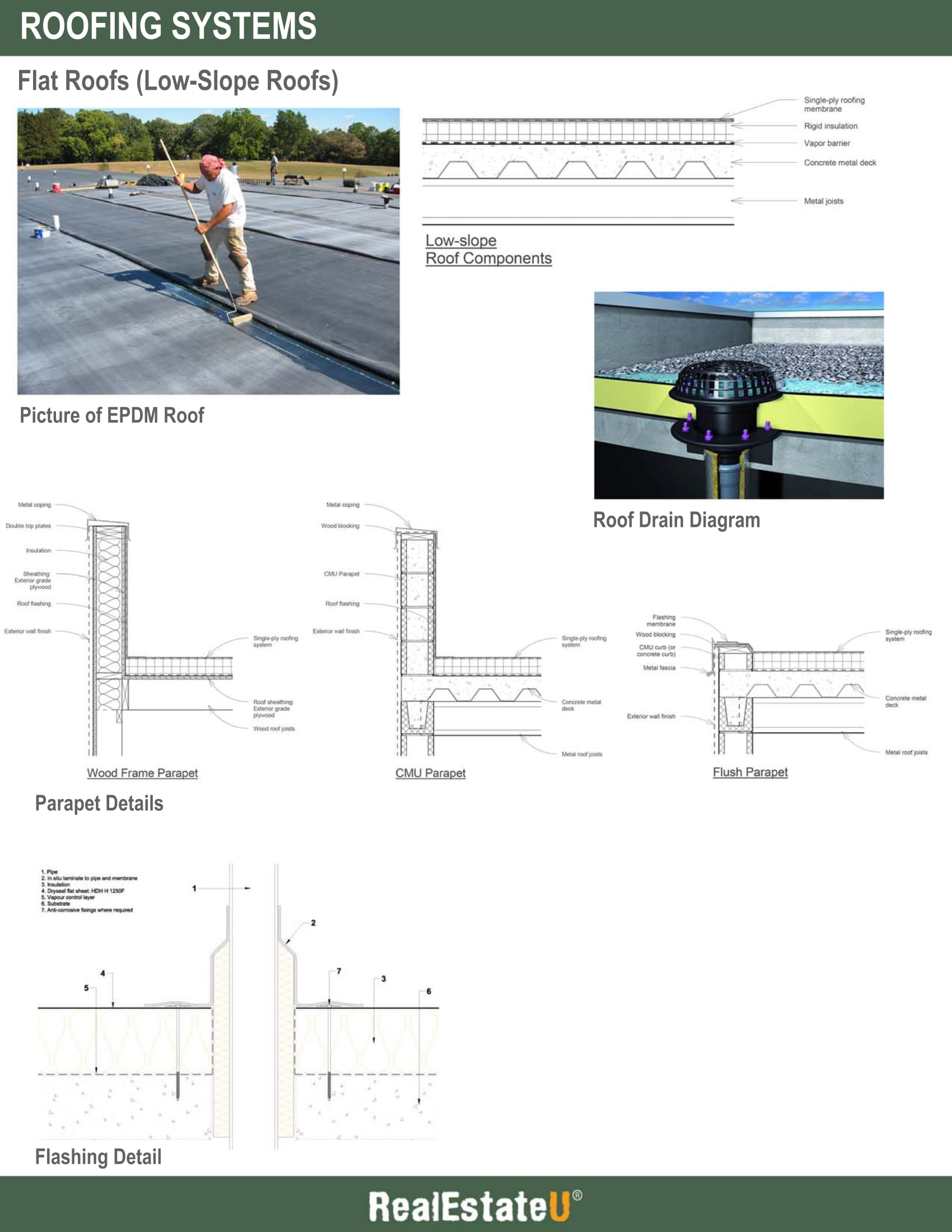
Next, we’ll discuss flat roofs, or low-slope roofs, which consists of a different roofing system.
While most residential buildings have a sloped roof, some may be built using a flat roof.
Rather than using rafters, a flat roof is built using joists, similar to that of a typical floor (although the roof load is typically less than a floor load).
You will often see flat roofs on multi-family residential buildings, with CMU bearing walls and metal joist construction. A concrete metal deck (or even just a metal deck) is installed on top of the roof joists. Then the insulation and roofing membrane are added to complete the roof assembly.
Despite its name, flat roofs almost always have a slight slope, which is why they are also referred to as low-slope roofs. The minimum pitch should be ¼”, which means for every 1’-0” in length, the roof riser ¼” in height. The roof must pitch to roof drains. The roof drains are located at the low points of the roof, while the high points are typically located at the parapets.
The slope in the roof can be accomplished in two ways. The insulation can be tapered, or the roof joists themselves can be sloped (a method preferred by roofing manufacturers).
A single ply roofing membrane is typically used on a flat roof. A single ply membrane is a waterproof layer that is applied in liquid or sheet form, over rigid, or semi-rigid insulation. The single ply membrane and insulation are then mechanically fastened to the roof deck below. A vapor retarder should be installed between the roof deck and the insulation, to prevent moisture from condensing below the roofing system.
The most common single ply roofs are EPDM and TPO. EPO (ethylene propylene diene terpolymer) is a thin, but extremely durable synthetic rubber roofing membrane. It is made of ethylene and propylene, which are derived from oil and natural gas. EPDM is available in white, but is most commonly identified as a black roofing membrane.
TPO (thermoplastic polyolefin) is stronger and more durable than EPDM. It is most commonly available in white and grey (although black TPO is available) and does not degrade under UV radiation.
Both EPDM and TPO are inexpensive and easy to install. They also offer warranted life-spans of 25-30 years. On the downside, these types of roof typically leak more often than sloped roof because of the many seams inherent in their design, and water ponding that may occur. If a leak occurs, it is difficult to identify its source since the water will most likely travel horizontally along the roof deck, before finding its way into the building.
As mentioned above, flat roofs are typically drained using roof drains. The roofing system slopes to the low points in the roof, where a drain will be located. The drains are then piped through the building, down to the building storm water outlet.
Parapets are located at the edge of a flat roof. A parapet is a low protective wall that aligns with the exterior walls of the building. In many instances, the parapet is simply an extension of the exterior wall.
Parapets are used for several reasons. First, many building codes require parapets to help prevent the spread of fire to the roof, from the upper floors of a building. Second, parapets provide a vertical surface to flash, and terminate, the roofing membrane (discussed shortly). Finally, a parapet may be included for aesthetic reasons.
Parapets may be made of wood or metal studs, CMU, or brick. In many instances, the parapet material matches that of the exterior wall. Parapets are typically topped with a metal cap.
In some cases, a flat roof building may have a flush perimeter detail.
A very important detail in any roof, both sloped and flat, is flashing. Flashing is a form of weatherproofing that includes pieces of impervious material installed to prevent the passage of water at a joint or penetration. Special attention must be given to all roof joints and penetrations, as these areas are the main sources of water leaks in a building. Penetrations may include pipes, vents, skylights, drains, chimneys, or dormers, among others.
Most flashing is made of metal, plastic, or rubber, depending on the location. For parapets and pipe penetrations, the flashing will match the roofing material. For chimneys or skylights, stainless steel metal flashing may be used.
Where possible, counter flashing should be used. Counter flashing is typically made of stainless steel or aluminum and is used to protect the termination of the flashing. It offers additional protection and reduces the chances of a leak.
Key Terms
35.5 Flooring Systems
Transcript
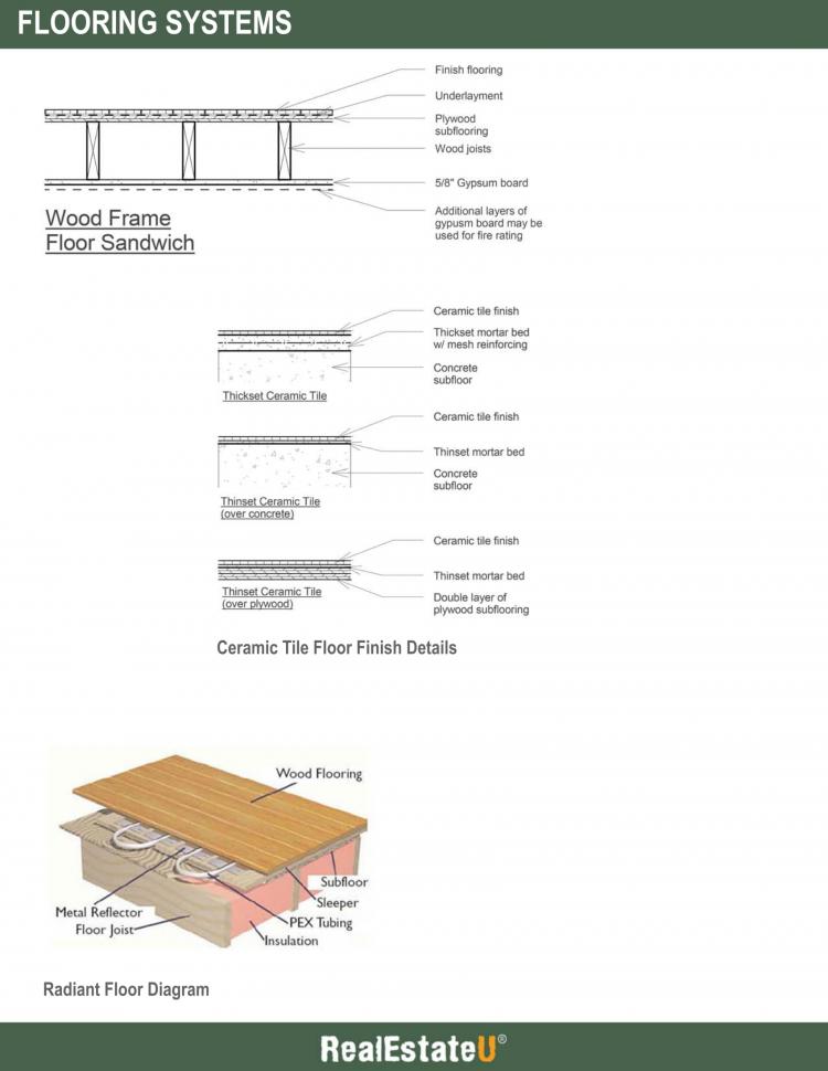
In this lesson, we will discuss the typical ‘floor sandwich’ you will encounter as a real estate agent. The floor sandwich refers to the flooring system and finishes, starting from the ceiling finish to the floor finish.
Let’s start by discussing wood floor finished.
The most common floor finish is wood flooring. Wood flooring consists of both hardwoods and softwoods that are laid in the form of flooring strips, planks or blocks. Bamboo flooring is also considered a wood floor finish, although it is actually a form of grass.
Common species of hardwoods include oak, maple, birch, and cherry. Common species of softwoods include southern pine, douglas fir, and hemlock.
Wood flooring is easy to install and maintain, and very durable.
Wood strip flooring is composed of long wood stripes that are 3 ¼” wide or less. They are installed using tongue-and-groove joints along the edges.
Plank flooring is installed in a similar manner to stripe flooring, the main difference between the two being plank flooring consists of members that are 3 ¼” to 8” wide.
Both strip and plank flooring can be placed in a variety of patterns including a straight single run, staggered joints, herringbone, or wicket.
Block flooring consists of square units that are prefabricated and then laid in place to form a pattern, such as a parquet or basket weave pattern. Block flooring also utilizes tongue-and-groove joints.
The most common type of wood flooring is known as engineered wood flooring, which consists of two or more layers of wood in the form of a plank. The layers of wood run 90 degrees to each other to achieve a higher level of strength and stability.
Wood veneer flooring is also used, which consists of a thin layer of wood over a core that is commonly a composite wood product. Wood veneer products are cheaper than engineered wood, however, they are not as durable.
In some applications, an underlayment layer may be added beneath the wood finish. The underlayment may consist of plywood, cement board, or a foam and cork material. The underlayment provides a smoother surface to install the finish floor and provides additional stability. In new construction, the use of an underlayment may not be needed.
In large spaces, an expansion joint should be provided at the perimeter of the wood floor, along the wall (below the baseboard). The finish floor will continuously expand and contract due to moisture in the room, and temperature changes. The expansion joint will allow enough room for the floor to move. If a joint is not provided, you may experience cracks in the finish floor or see wood members begin to ‘pop’ out of place. The expansion joint should be at least ¼” wide.
Next, we’ll discuss ceramic tile floor finishes.
A ceramic tile floor finish is common in bathrooms and kitchens. Ceramic tiles are relatively small, modular surfacing units made of clay or other ceramic material. They offer a durable and water-resistant finish that is difficult to stain, but easy to clean. Ceramic tiles may be glazed or unglazed.
Ceramic tiles can be laid using a thin set process or a thickset process. In a thinset process, the ceramic tiles (½” to ¾” thick) are laid in a 3/16” - ⅜” bed of mortar. A thinset tile floor must have a durable subfloor that minimizes deflection. You will typically see a subfloor consisting of ⅝” plywood with an additional ½” or ⅝” layer of plywood that serves as an underlayment.
In a thickset process, the ceramic tile is laid in a 1 ¼” - 2” thick mortar setting bed, which is often reinforced with metal lath or mesh. The advantage of a thickset floor is that any deflection in the floor joists and subfloor can be absorbed by the setting bed, resulting in less cracking in the tile itself. The thick setting bed also allows the finish floor to slope to a drain. However, a thickset floor is heavy and demands a more robust floor structure, such as concrete metal deck.
Let’s take a moment to discuss radiant flooring.
An increasingly popular floor finish is radiant flooring. Radiant flooring systems utilize pipes or tubing carrying hot water, or electric resistance heating cables. The radiant heat that is given off is absorbed by surfaces and objects in the room and raises the ambient temperature in the space.
Radiant flooring efficiently heats the space and often results in lower heating costs. On the downside, however, radiant heat takes longer to heat up a space. For this reason, supplemental heating sources may also be installed.
Now, let’s go over the various ceiling finishes you may encounter in residential construction.
The most common ceiling finish consists of ⅝” gypsum board, which is fastened directly to the underside of the floor joists. Type ‘X’ gypsum board may be used to help achieve a fire rating, especially in wood frame construction.
The gypsum board is then painted.
If a lower ceiling, or soffits are desired, cold formed metal framing (or wood framing) can be used to build out the desired configuration. The gypsum board is then fastened to the framing.
Key Terms
PLEASE REVIEW THE DOCUMENT BELOW:
35.6 Interior Elements
Transcript
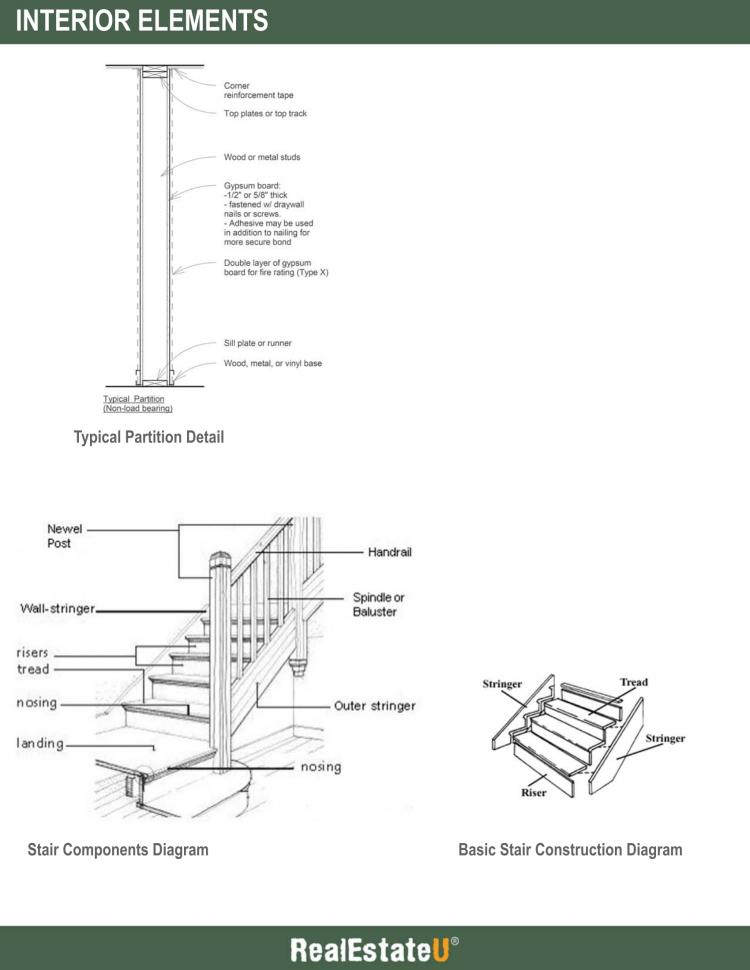
In this lesson, we will discuss the two main interior elements of a residential building, namely, interior partitions and stairs.
Interior partitions are non-load bearing walls that are used to form the spaces of a building. Interior partitions are made of cold-formed metal framing, or wood framing, and finished with gypsum board.
The primary support component of a partition are studs that are placed, 12”, 16”, or 24” on center. In wood frame construction, the bottom of the stud wall includes a sill plate, while the top includes a top plate. The sill and top plates are typically the same size as the studs. In cold formed metal framing construction, the bottom of the stud wall includes a runner channel, while the top includes a ceiling runner channel.
A layer of ⅝” gypsum board is then fastened to the stud wall. A wood or vinyl baseboard is typically added to conceal and finish the joint at the floor.
If a wall needs to be fire rated, layers of ⅝” type X gypsum board are used.
In wet spaces, such as bathrooms, water resistant gypsum board is used.
Interior stairs in residential construction are typically made out of wood and used to connect levels, and provide a means of egress.
The basic construction of a stair consists of a risers, treads, and stringers. The risers are the vertical face of the stair, the treads are the horizontal steps, and the stringers are the primary support for the stairs, located on each side of the stairs.
Building codes regulate the minimum and maximum dimensions of risers and treads. The most common formula that building codes use is the following:
Tread (inches) + 2x Riser (inches) = 24” to 25”
In addition, the maximum riser in residential construction is typically 7”, while the minimum tread depth is 11”.
The minimum width of a residential stair is 36”. However, wider stairs, such are 44” - 60”, are preferred as they are more common and practical.
The depth of the landings should be at least the width of the stair. For long, straight-run stairs, building codes generally require a landing every 12’-0” in vertical rise.
Handrails are required for all stairs. Handrails should be mounted 34”-38” above the stair treads or nosing.
Key Terms
PLEASE REVIEW THE DOCUMENT BELOW:
35.7 Exterior Walls
Transcript
In this lesson, we will review the typical exterior wall construction found in residential buildings.
Residential exterior walls are composed of several layers, which each serve a purpose. These layers include:
- A structural component,
- Sheathing, a vapor barrier and insulation,
- An exterior finish; and,
- An interior finish.
Let’s start by going over the structural components of an exterior wall.
Exterior walls in residential houses and small buildings are almost always load bearing walls. In essence, these walls are structural in nature with “punched openings” for windows and doors. The structural component of exterior walls is typically built out of stud framing (both wood and cold formed metal framing) and CMU.
In stud walls, the studs are built 12”, 16”, or 24” on center. Horizontal channel bracing may be added for additional support.
CMU in exterior walls may consist of 6”, 8”, or 12” wide block, which can be reinforced both vertically and horizontally. If vertical reinforcement is added, the CMU cells will be grouted solid.
Next, we have the exterior sheathing, a vapor barrier and insulation.
In stud construction, insulation is added between the studs. You will typically see batt insulation installed the full width of the studs. A vapor barrier may be added to the inside face of the stud wall (on the warm side of the insulation) to prevent moisture from entering into the exterior wall cavity.
It is important to note that adding insulation between the studs may not be very effective. The studs, especially metal studs, create what is called a thermal bridge. In essence, the studs become thermal conductors, which leads to significant heat loss. In many cases, the insulation will be 40% less effective due to thermal bridging. The solution to this problem is to provide an additional layer of rigid, or semi-rigid insulation on the outside face of the sheathing. This will prevent studs from being in direct contact with cold air.
Exterior sheathing is added on the outside face of the studs. Sheathing is made of ⅝” exterior grade gypsum board or plywood. The sheathing helps brace the stud wall, creating more stability in the structure.
In CMU construction, a vapor barrier is applied to the outside face of CMU (typically fluid applied) with rigid, or semi-rigid insulation added on top.
Next, we’ll cover exterior finishes.
There are several common exterior finishes used in residential construction. These include wood siding, stucco, and brick veneer.
Wood siding is most often used in stud construction. It consists of horizontal boards that are fastened through the exterior sheathing, and into the stud wall behind.
Behind the wood siding is permeable building paper that allows any water vapor in the wall to escape to the outside.
The siding is available in different forms. Bevel siding, or lap siding, is made by overlapping tapered boards and nailing each board above the overlap.
A shiplap siding consists of boards joined edge to edge with overlapping rabbeted joints.
A stucco finish is used in both stud and CMU construction. Stucco is a course plaster composed of portland cement, sand, and hydrated lime, mixed with water and applied in a plastic state to form a hard covering for exterior walls.
In stud construction, stucco is applied in three coats over waterproof building paper and metal lath. The thickness of the stucco is around ⅞” thick.
In CMU construction, stucco is applied in two coats and is around ½” thick.
Stucco is available in different finish coats, ranging from a fine texture to course.
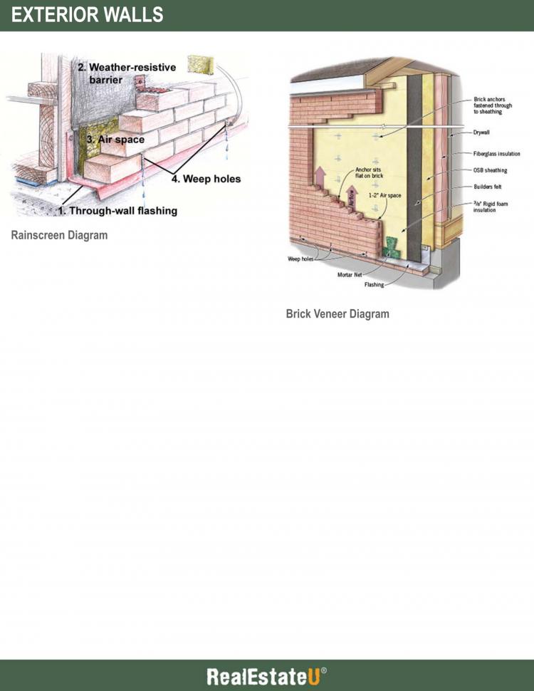
Brick veneer is a very popular exterior finish. If you see a brick finish on a building, what you are seeing is not a solid, structural brick wall. Instead, it is a thin decorative element that is tied back to the structural wall.
Brick veneer walls utilize what is known as a rainscreen system. In a rainscreen system, a pressure equalized air space is located between a wall cladding veneer and the air barrier, sheathing, and insulation. The idea is that the wall cladding will prevent most wind driven drain from reaching the air barrier, therefore reducing the chances of a leak. Any water which does reach the air barrier is weeped back out to the exterior by moving down the air space, to the flashing, and out weep holes at the bottom.
Brick veneer consists of a single wythe of common bricks (or building bricks) that are joined together using mortar. The nominal size of a typical brick is 4”x2 ⅔”x8”. The bricks are then connected to the stud or CMU wall using tiebacks, which provide lateral stability for the brick veneer. Tiebacks are installed every 6th course vertically, and 24” on center horizontally, and are embedded in the brick mortar joints.
An air space is provided between the brick veneer and insulation (or air barrier) behind. The air space should be at least 2” wide to allow water to drain out, and to ensure any mortar from the brick veneer does not clog the air space during construction.
At the bottom of the wall, or at the top of an opening, weep holes must be provided every 16” or 24” on center. The weep holes must be provided in the bottom mortar joint, at the flashing. This ensures any water in the wall cavity will drain properly to the exterior.
The flashing is an important component of a brick veneer wall. It is located at the bottom of the wall system and at the top of a wall opening (window or door). Flashing is typically made of metal (stainless steel or aluminum) and bent to form a slope, down and away from the wall. It is secured to the structural wall behind and terminates just outboard of the brick veneer. A lip should be included on the exterior to ensure water drips away from the wall.
Finally, we have interior finishes.
The inside face of an exterior wall is not much different than an interior partition.
In a stud wall, ⅝” gypsum board is fastened to the studs. If a fire rating is needed, layers of type X gypsum board are used.
In CMU wall construction, gypsum board cannot be fastened directly to the CMU. Instead, ⅞” or 1 ½” furring channels are installed, and the gypsum board is fastened to the furring channels. Studs can also be used if insulation needs to be installed on the inside face of the CMU wall.
Key Terms
PLEASE REVIEW THE DOCUMENT BELOW:
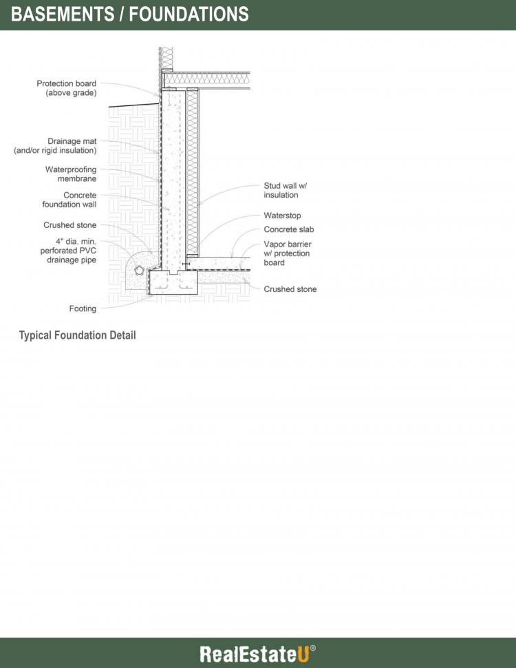
35.8 Basements / Foundations
Transcript
In this lesson, we’ll briefly discuss basements and foundations, what are the lowest part of a residential house or building.
A basement is formed by the foundation walls of a building. When foundation walls are enclosing habitable space, they must be constructed in a way to eliminate the penetration of water and soil gases such as radon, control heat flow, and accept a range of interior finishes.
Waterproofing must be applied to the outside face of the foundation walls, down to the bottom of the footing. It is also good practice to have the membrane extend at least 6” above grade. The waterproofing membrane may consist of rubberized asphalt or butyl rubber.
The waterproofing membrane should then be protected to avoid any punctures from the backfill soil. The membrane is commonly protected by rigid insulation or a drainage mat. Above grade, the membrane can be protected using a protection board, or metal flashing. The membrane should not be exposed to the sun.
The inside face of the foundation wall can be built out using studs, insulation, and gypsum board. The studs provide a means to mount the gypsum board, while insulation is used between the studs.
A continuous footing drain, made of perforated PVC piping, should be provided 2” from the top of the footing. The drain should be at least 4” in diameter and protected by a filter fabric, surrounded by 6” minimum of crushed stone (to allow better drainage).
The footing drain should ultimately drain to a storm sewer, dry well, or natural outfall on site.
The concrete slab that forms the floor of the basement should be reinforced and at least 4”-6” thick. A vapor barrier should be provided beneath the slab to prevent moisture from entering the basement. This is especially important if the owner intends to provide a finish on top of the concrete slab, such as vinyl flooring. If a vapor barrier is not provided, there will be a high risk of mold growth beneath the floor finish.
A protection board made of asphalt fiberboard or rigid insulation may be provided between the vapor barrier and the concrete slab to avoid any punctures during construction.
At least 4”-6” of crushed stone should be provided beneath the vapor barrier in order to reduce the hydrostatic pressure generated from water in the soil.
Key Terms
PLEASE REVIEW THE DOCUMENT BELOW:
COPYRIGHTED CONTENT:
This content is owned by Real Estate U Online LLC. Commercial reproduction, distribution or transmission of any part or parts of this content or any information contained therein by any means whatsoever without the prior written permission of the Real Estate U Online LLC is not permitted.
RealEstateU® is a registered trademark owned exclusively by Real Estate U Online LLC in the United States and other jurisdictions.